Dock height and truck bed height will determine the operating grade of the dock leveller. The general selection criteria is the maximum grade percentage from dock to vehicle: when using electric powered handling equipment it is 10%, and for gas or diesel powered equipment 15%. Exceeding these grade percentages may result in equipment "hang up", damage to handling equipment and load spillage.
Vehicle beds range from 30" to 62" (762m to 1575mm) in height. The question is: what vehicles will be serviced at the facility with the greatest frequency? Once this is determined, all or a majority of the docks should be made to accommodate this bed height.
A dock area should be flexible enough to accommodate any vehicle. The most common dock height is 48 52 (1219 to 1321mm).
Substantial height differences between dock and trailer can create severe dock leveller grades, decreasing the overall effectiveness of the operation.
Improper applications and use of dock levelers when there is a severe grade difference can lead to damage and premature failure of the dock levelers. Customized dock levelers can be made to suit unique applications and offset the height difference.
Flush docks are in most common use today. Here the face of the dock (foundation) is flush with the outside wall of the building. To prevent wall damage and protect dock seals (if used) on a level approach it is recommended that the foundation/dock bumper extend 4" (101.6mm) beyond the outside wall.
Note: If building wall projects beyond dock face additional foundation/bumper projection is required.
Enclosed docks are generally used when climate control, product protection, security, and overhead lift capabilities are required.
They are not a common choice due to high construction costs and vehicle exhaust pollution considerations.
Open docks, although they may be necessary alternative in some cases, are not generally recommended because of their weather exposure and susceptibility to pilferage. In all cases these docks should be provided with a canopy. And in situations where canopies are planned over docks on sloped grades, the height of the canopy must be calculated to accommodate the height of the sloped trailer.
Depressed docks with slope driveways are used where building construction eliminates basements and dock level floors. Caution must be exercised in planning the grade of the driveway. It should not exceed 10% in order that the top of the truck will not hit the wall of the building, cargo topple, or that pull-away traction problems result in ice or snow conditions. Recommended Bumper Projection Chart
Saw tooth docks present a design solution to situations where apron space is limited, however they reduce useable dock space.
The majority of trucks on the road today are at least 8' wide, and an increasing number are 8'6" wide. An 8' door width can service these trucks, but maneuvering room is limited. Another concern of 8' door widths is off-center truck positioning. This can lead to further reductions in efficiency and even create the need for repositioning of the vehicle.
Ideally, nine-foot wide doors should be used to service 8'6" wide trailers. Side-by-side palletizing is simplified and the potential for product damage is significantly reduced. Nine-foot wide doors can also accommodate the unplanned servicing of many oversized loads. For special applications with oversized loads, a 10' wide door can be incorporated.
Wider doors require more building space which can create a problem when room is restricted.
Keep in mind the maximum overall limits for trailer size are 8'-6" wide x 13-6 high (different in some states). Flat bed carriers are able to exceed the maximum width dimensions (special permits are required).
Door should be spaced on 12 centers to accommodate the majority of vehicles, the use of dock seals / shelters, and the mounting of two-way communication light systems.
Trailers can range in height from flatbed units (approximately 48" / 1219mm) to closed vans (162" / 4115mm from ground level). The highest internal height for product loading is approximately 114" (2896mm) high.
Depending on the application, there are three basic door heights that are typically specified. Keep in mind that the common dock height is 48" - 52" (1219 - 1321mm).
8' (2438mm) high doors can accommodate many loading/unloading operations, but do not facilitate full floor to ceiling loading of product. The need to optimize the available height in a trailer when loading product in an effort to minimize freight costs, this need makes the 8' high door a less desirable choice.
A 9' (2743mm) high door permits improved floor to ceiling loading of product because a higher load can easily pass under the door opening. Fuller and tighter loading is possible with a reduced risk of product damage due to product impact with the door header. The nine foot height is a popular door height because it suits a wide range of applications. However, trailers with lower heights may create a gap at the top of a 9' door. This gap can be sealed with an appropriately sized dock seal or shelter.
A third typical door height is 10' (3048mm)
The most versatile door size is 10' (120") high. This height will service the full range of loading / unloading operations. 10' high doors will accommodate trailers of all heights up to and including high cube trailers and high cube sea containers.
Special consideration should be given when choosing a dock seal or shelter for a 10' high door. A dock shelter with a 10' high door provides the greatest degree of unobstructed access to the rear of the trailer.
Door sizes can be specified to any configuration required. Keep in mind the product characteristics and possibility of future change.
Selecting the proper capacity for the leveller can be confusing due to the variables that must be addressed. Dock leveller manufacturers have different terminology to describe capacity such as rated load, dynamic capacity, rollover capacity, etc., which can add to the confusion. To ensure proper capacity selection, consider these factors:
A simple guideline exists to calculate the safest dock leveller capacity for light to normal usage. Add the gross weight of the vehicle and the gross weight of the load. Multiply that by 2.5 (ie. 8,000 lbs. forklift gross weight + 4,000 lbs gross load = 12,000 lbs x 2.5 = 30,000 lbs; rounded up to 30,000 lbs).
If the manufacturer does not offer that exact capacity, use the next higher capacity. For normal to heavy usage, a multiplier of 3 to 4 should be applied.
Specifying a capacity higher than the calculated requirements will further extend the life expectancy of the dock leveller. Select the dock leveller to offer a minimum of 10 years of service life.
Dock levelers are designed to withstand dynamic forces generated when the loading vehicle makes contact with the inclined leveller.
The impact force can be many times greater than the actual gross load due to the speed at which it is traveling. Three-wheeled loading vehicles or narrow wheels greatly increase pin-point loading and should be accounted for by further increasing the leveller capacity. When using equipment of this type, a dock leveller with a minimum capacity of 30,000 lbs. is recommended regardless of gross load.
This guideline will work in the majority of applications when the grade is less than 7%, the speed does not exceed 5 mph, and the frequency is not more than 8 trucks per door per day, 20 rollover cycles per vehicle. The rated capacity may be adversely affected by unique loading or operating conditions.
For applications of higher frequency, greater grade, and higher speeds, a multiplier of 4 to 5 times the total gross load should be used. Unusual conditions can lessen the effectiveness of this guideline. When in doubt, always specify a higher capacity.
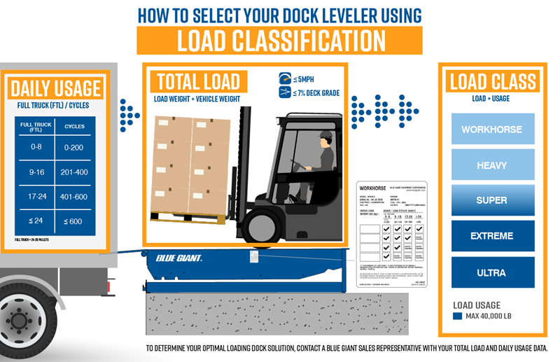
Correctly selecting a load classification for your distribution needs is vital. It will maximize the lifespan and use of our product. Read above to correctly select the class and identify your usage and load.
Please contact a Blue Giant Representative with your total load and daily usage data for a complete submittal for your needs.
Blue Giant dock levelers are available in several standard widths 5'-0", 6'-0", 6'-6" and 7'-0" widths, depending on the specific model. The majority of trailers overall widths being 8'-6" wide, with an inside width of 8'-0", the 6'-0" wide dock leveller is adequate for most facility operations, allowing for safe fork truck traffic at speeds less than 4 mph and the ability to accommodate narrower trailers.
However, if your facility usually loads pallets side-by-side, a wider dock leveller should be considered. The wider dock leveller allows the best access for below dock and end loading access for side-by-side pallet loading/unloading. The extra dock leveller width allows for straight-in and straight-out fork lift traffic. This avoids time-consuming maneuvering when the loads approach the rear of the trailer. The wider dock leveller provides greater below dock access, where dock leveller pit walls may interfere with fork lift traffic access to loading/unloading materials from the trailer.
Wider dock levelers also aid in protecting against the accidental "edge-zone", which can occur at the side(s) of narrower dock levelers. When a fork lift gets caught in the "edge-zone" it is unsupported by the dock leveller and the possibility of dock separation can occur, which can lead to a crippling or fatal accident.
Blue Giant dock levelers are available in several standard lengths of 5'0", 6'-0", 8'-0", 10'-0" and 12'-0" lengths, depending on the specific model. One of the most important consideration in dock leveller length selection, is the consideration of dock to truck bed height ranges and underclearance requirement of the material handling equipment used to load/unload material from the truck. Added dock leveller length lowers the dock leveller grade in and out of the truck, increases dock safety, adds to dock leveller life, reduces potential for spillage/damage of materials and increases loading dock efficiency.
Maximum Height Differential (Dock to Truck Bed) Chart depicts general material handling loading equipment grades to height difference and dock leveller lengths.
Note: Consult material handling loading equipment manufacture for recommended maximum grade capabilities.
Blue Giant dock levelers lips are available in several lengths of 16", 18", 20" or 24" lengths depending on the specific model. The standard industry lip length for loading dock levelers is 16". Dock leveller lip at a minimum needs to maintain 4" to 6" effective lip contact with the bed of the truck/trailer. Proper lip projection requires consideration of the dock bumper thickness, the truck/trailer bumper thickness, driveway approach, as well as truck/trailer bed recess at the back end of the truck/trailer. Typically longer lips will always be required when refrigerated trailers are used.
Total Recycled = 23% Post-Industrial = 85% Post-Consumer = 6%
What the above means is that of the 23% total recycled content of our product, 85% is post-industrial content, and 6% is post-consumer content.
All dock equipment (including restraints) is accredited for MR Credit 4 (Recycled Content) and MR Credit 5 (Regional Materials), which means that steel is brought to our manufacturing facility from less than 500 miles away.
All dock levelers are accredited for EA Pre-Req 2 (Minimal Energy Performance) because of their hydraulic or air powered lips. Mechanical levelers are additionally accredited for EA Credit 1 (Optimized Energy Performance).
All dock seals are accredited for EA Pre-Req 2 (Minimal Energy Performance) and EA Credit 1 (Optimized Energy Performance).
Vertical storing dock levelers achieve both MR Credit 4 and MR Credit 5 as well as EA Pre-Req 2 and EA Credit 1. When paired with an inflatable dock seal, the vertical storing dock leveller is an excellent choice when quoting LEED certified projects.
The following information is a quideline for applying truck service to the loading dock area to insure proper design, safety and service to your loading dock area. Apply proper Traffic Engineering design standards and compliance with local codes.
Suggested minimum width at gates leading into approach roadways is 16' to 20' (4.9m to 6.1m) for one-way traffic, 30' to 32' (8.7m to 9.3m) for two-way traffic, and 38' (10.7m) if pedestrian walkway is to be included.
Trucks should be permitted to drive in rather than back in. Straight-through, "Y" or angle approaches should be considered depending on traffic volume estimates.
If mixed passenger car and pedestrian traffic is involved in the approach, suitable seperation and safety precautions should be planned for.
Service roads for one-way truck traffic should be a minimum of 14' (4m) wide, for two-way traffic no less than 26' (7.8m) wide. If pedestrians are to be accommodated, there should be an additional 6' (1.6m) lane separated from the roadway by a physical barrier.
If a right angle intersection is required, a 50' (15.2m) radius should be planned for commercial vehicles.
he design of approach roadways should also allow for counterclockwise traffic circulation since it is easier for drivers to make left-hand turns and to back trailers into a dock from this position.
The configuration of the area required to maneuver and position trailers into place is called the apron space. Planning apron space requires recognizing trailer movement and the amount of room it takes to achieve that movement.
Traffic flow and vehicle length are key factors for consideration (ie. a truck with an overall length of 65' requires a minimum apron space of 135).
If the area is to be surfaced with asphalt, a concrete landing strip must be poured. In warm temperatures, the landing strip will prevent the trailer's landing gear from sinking into the asphalt when spotted. Typical position of semi-truck landing gear is 120" (3048mm) behind the nose of the trailer. Gravel-covered apron space should be avoided because it creates uneven, unsafe conditions.
Unless docks are designed to handle peak loads, provision must be made for a truck waiting area. This should be placed so that the trucks in this area do not interfere with trucks maneuvering into or pulling away from the dock.
These surfaces should be specified to be evenly laid and structurally sound to support heavy wheel loads. All roadway surfaces should be slightly crowned and properly equipped with drainage outlets.
An ideal design is a slightly inclined approach that does not inhibit the positioning of trailers, but allows water runoff away from the building. This also helps prevent the potential of damage to the building from trailers that are severely angled when positioned by jockey trucks.
Declined approach areas are constructed when the floor of the building is even with the exterior grade level. To achieve a proper dock height for truck loading/unloading operations, the approach to the dock needs to be built incorporating a decline to the building.
There are some issues of concern with a declined approach to the dock. These include: difficult snow removal, water drainage, buildup of debris, and high impact forces to the dock. There is also the potential for serious damage to the building wall from impact by the top of the trailer. Approaching trucks can generate severe impact forces from only a short distance. Increased bumper projection or a projected dock must be provided to avoid building damage.
Special considerations must be made when incorporating other loading dock equipment with a declined dock approach. Dock seals need to be tapered to match the angle of the trailer. If the seals are not tapered, effective sealing will not be accomplished and dock seal damage is likely. Vehicle restraints must also be projected sufficiently to ensure proper operation and safety.
Overcoming impact to the building wall is easily accomplished. For new construction projects, the dock can be projected sufficiently to prevent the top of the trailer from impacting the building wall.
Required projection is determined based on the percentage of grade. To calculate the grade, measure the difference in height from the dock to a fixed point approximately 50' directly out from the dock. Divide the height difference by the length measured, using inches (eg. 18" difference over 600" distance. 18/600 = .03 x 100 = 3% grade) Declined approaches should not exceed a 10% grade for proper and efficient dock operations.
% of grade: (R1-R2) Run (R3)
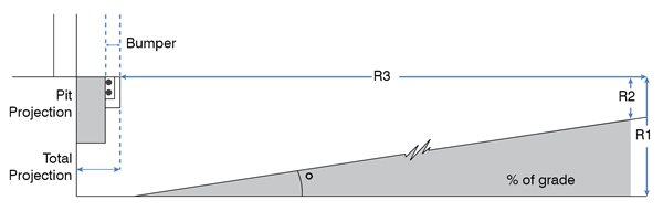
This configuration protects the building from trucks backing in.
Projection length increases proportionately to amount of decline or incline. If installing restraints, extensions plates must be ordered with the same projection.
Dock lip penetration (purchase) must be considered with projections and bumper sizes. A minimum of 4-6" lip penetration is required for safe dock operations.
Loading dock bumpers protect the dock from the impact force of backing trucks/trailers, that can cause structural damage to the loading dock, dock equipment and building. The impact force of an approaching truck/trailer can generate up 300,000 lbs. of impact force. The impact resilience and strength of dock bumpers can aid in preventing damage from occurring. Blue Giant provides several styles of dock bumper designs, and a general guideline of factors to consider when applying dock bumpers for your application needs.
Blue Giant dock bumpers are available in "molded" and "laminated" styles, with an optional steel face plate available, depending on the specific model.
Blue Giant dock bumpers are available in three (3) standard thickness of 4", 4.5" and 5.5", depending on the specific model. Dock bumper thickness of 4" - 4.5" is suitable for most standard application, to effectively protect the dock from the impact forces of backing trucks/trailers. For moderate to heavy traffic applications a 5.5" thick dock bumper provides greater impact absorption ability. Caution should be taken when increasing bumper projection beyond standard which can reduce the loading dock levelers lip projection onto the bed of the truck/trailer.
Note: If greater bumper projection is required consider Cantilevered Docks and Pit Projections or bumper build-outs of proper strength and construction, while maintaining proper dock leveller lip projection upon the bed of the truck/trailer. Replacement cost of standard style dock bumpers vs. extra-thick dock bumpers can be a dramatic life-time cost savings
Blue Giant dock bumpers are available in several heights, 10", 13", 18", 20" and 30", depending on the specific style and model. Docks servicing air-ride-trailers should consider the vertical height of the loading dock bumper closely, for the maximum raised and lower height for air-ride-trailers arriving at the dock. When air is released from suspension system, of an air-ride-trailer, the bed can plunge downward causing the trailer to loose contact with the loading dock bumpers. The result can cause the trailer to become a "giant pry-bar" which can damage the dock and short vertical height dock bumpers.
Raised bumper brackets should be consider when a truck/trailer bed height is higher than dock height. Applying raised bumper brackets can prevent damage to the dock equipment and structural damage to the building wall.
Steel face plate bumpers are used for high frequency/heavy impact applications, where yard jockey trucks are used for trailer positioning and/or when air-ride-trailers are encountered. A steel face plate on your loading dock bumper, offers protection against unusual wear, provides smooth transition for trailer travel during loading/unloading and greater life for your dock bumpers - which can reduce the frequency and cost of replacing dock bumpers in the future.
When portable dock plates are considered, dock bumper spacing must allow for the dock plate's vertical support legs to fit between the chosen bumper spacing. With the truck/trailer spotted solid against the dock bumpers, the 4" to 5.5" bumper projection will allow for the insertion of the portable dock plate support legs.
Note: Confirm dock plate's vertical support legs spacing with client and/or dock plate manufacturer.
There are multiple ways to mount dock bumpers to the loading dock. The drawings below show several examples of installed dock bumpers; first example shows dock bumpers mounted to an open dock application and second example shows multiple details on dock bumper mounting for recessed dock levelers.
Dock bumpers can be affixed by several means of anchoring to a well constructed loading dock, as noted below;
Blue Giant offers several loading dock pit construction methods that assist in saving time, money and effort in installation requirements for your loading dock leveller. Selecting the appropriate method is a critical step in establishing a safe, secure and efficient loading dock, at time of construction.
Several loading dock pit construction methods are available from pre-installed pour-in pan dock levelers, prefabricated pit kits and curb angle sets. Contact your Blue Giant dealer to help assist with proper selection to your unique construction need.
Improve construction site safety and reduce liability of having an open loading dock pit. Pre-installed pour-in pan dock levelers, save time, money and effort in building a square pit for all models of standard loading dock levelers. Pour-in pan dock levelers eliminate the need for pre-pit forming, simply set and install the pour-in pan dock leveller onto the pre-poured dock pit floor.
Provides all the construction advantages of a pour-in dock leveller while eliminating the problems of handling and positioning the dock leveller months before it is needed. Ensures accurate pit dimensions and squareness. First curb angle not shown.
Blue Giant offers several curb angle configurations are available with this style of pit construction, which include 4 PC, 6 PC and 8 PC curb angle kits.
Truck berth positioning involves the physical layout of the dock doors and levelers.
Truck berths should be at least 12' (3.7m) wide center to center of the docks and 14' (4.3m) widths should be considered if space and budget permit. The wider the dimension the greater convenience there is for storage and staging.